How to Build an AR-15
Written By
Kenzie Fitzpatrick
Competitive Shooter
Edited By
Michael Crites
Licensed Concealed Carry Holder
Share:
Products are selected by our editors. We may earn a commission on purchases from a link. How we select gear.
Updated
Jun 2025
Learning how to build an AR-15 is essential for not only custom ARs but also for developing a thorough understanding of how the parts and pieces of your rifle fit together.
This can help with triaging issues as you use it and for mastering the AR platform over time. This article is part of our ongoing series on Gun Basics.
In This Article
Before You Build Your AR-15
It makes no difference if your AR build is 5.56 NATO or .300 Blackout — make sure your build complies with any federal or state laws. If you are building an AR pistol or a short-barreled rifle, make sure the necessary paperwork is completed before assembling the gun. This can often be a good conversation to have at a local gun shop to ensure you’ve got all your ATF ducks in a row before you make your AR-15 come to life.
1. Safety First
If you’ve never disassembled a gun past field-stripping and cleaning, prepare for a few surprises along the way. Safety glasses are essential with rifle builds because detent springs and pins can go flying directly towards your eyes.
A shop apron with pockets and a pair of N440 gloves can help keep your clothes clean and hands safe as you begin hammering in pins. Plus they look mighty official if you ask me.
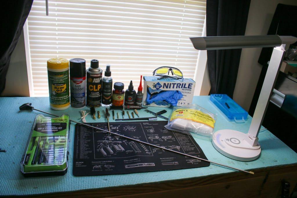
2. Clear Your Work Surface
Your work surface can make the build process easy or extremely hard. If you have access to a workbench or a long desk, this is preferable over something like a kitchen table. Always lay down a cleaning and maintenance mat over the surface and make sure no food, drinks, or clutter are present.
A bright work light, lamp, or headlamp will make assembling small parts and roll pins a lot easier to see.
It’s never a matter of “if” your springs go flying, but “when.” It’s surprisingly easy to lose small AR-15 lower parts, so if possible, lay out a towel on the floor where you are working or at least ensure the floor space is clean so you can spot parts easier.
3. Gather The Tools Required
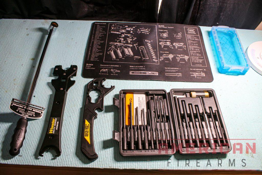
handguardbasic armorer’s kit can get you started with the necessities.
If you have a vice grip or install one on your workbench, you’ll have an invaluable tool for assembly. You will need an AR-15 combo tool as well as a torque wrench.
Invest in a good set of brass roll pin punches and hammer. The most underrated helpful tool in my opinion is a pivot pin installation tool — they make life so easy. You will also need an upper vise block clamp and a mag well vise block so you can assemble the barrel and castle nut to specs.
Use a lapping tool to ensure a perfectly square and true surface to attach the barrel. This is critical for accuracy in an AR-15 rifle.
The last item that can help keep pins and springs from rolling off your workspace is a small container similar to Tupperware or a bowl.
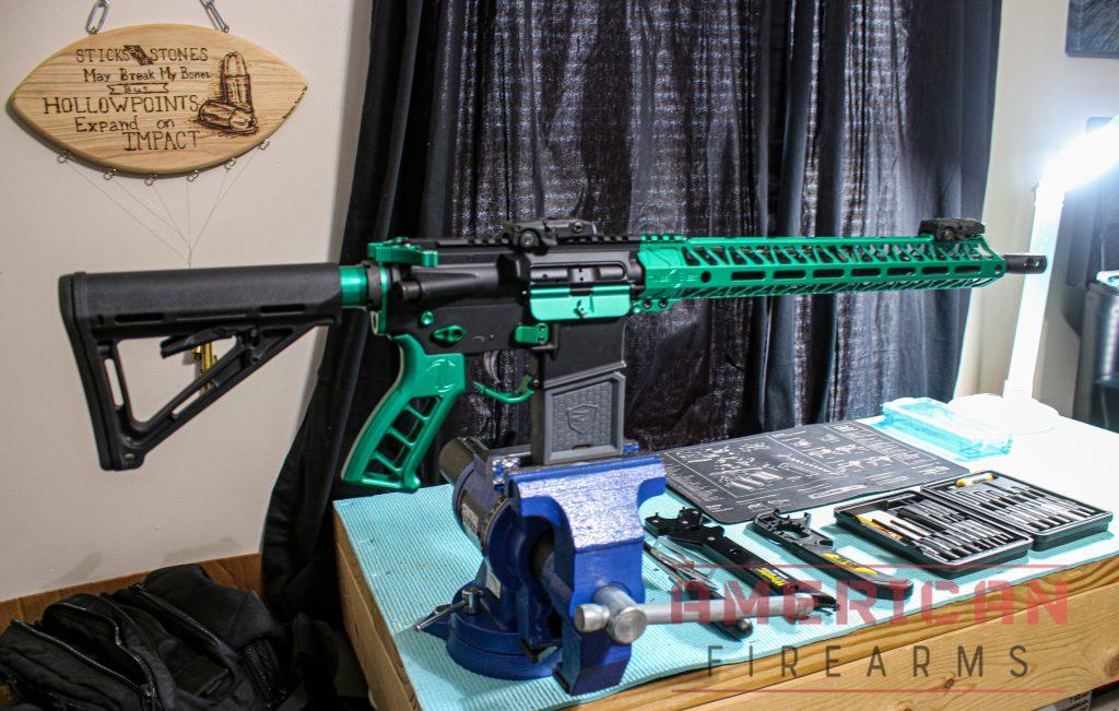
Start Building Your AR-15
When it’s time to assemble your AR rifle, use this guide as a reference to installing both your lower and upper assembly; following this guide step by step will ensure a successful build experience.
Rather than searching as you go, make sure all of your tools are laid out and your parts are together. If this is your first build, try not to mix the lower parts kit with the upper parts, as everything has its place and purpose.
1. Use a Cleaning and Maintenance Mat
A cleaning and maintenance mat is helpful for several reasons. When you are hammering parts out of your lower receiver assembly or upper, a mat provides a cushion, so the hard workspace doesn’t mar up the finish on your receivers.
Some screws and threads on your build need anti-seize or thread locker applied to them, and a mat will protect your workspace from overzealous application of the above.
AR-15 barrels and bolt carrier groups typically are greased when new; however, BCGs need oil applied before fitting into a rifle. A cleaning mat will protect these parts from picking up more debris from your workspace and provide absorption of any extra oil.
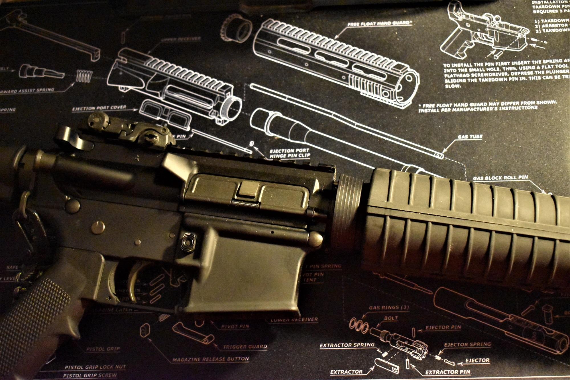
2. Install Forward Assist Assembly on Upper Receiver
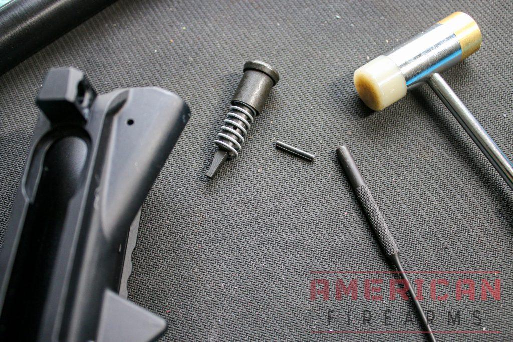
Parts Required:
- Forward assist
- Forward assist spring
- Forward assist pin
Steps:
- Starting with a stripped upper, the forward assist needs to be installed in the correct direction. The lever for the forward assist should push outward from the side of the upper receiver.
- Wrap the forward assist spring around the forward assist and push it into the upper.
- Using your middle finger to compress the forward assist, insert the roll pin into the hole and hammer it in.
- Once the pin is halfway in, check that the forward assist cannot come back out. If it doesn’t, finish hammering.
3. Install Ejection Port Cover Assembly on Upper Receiver
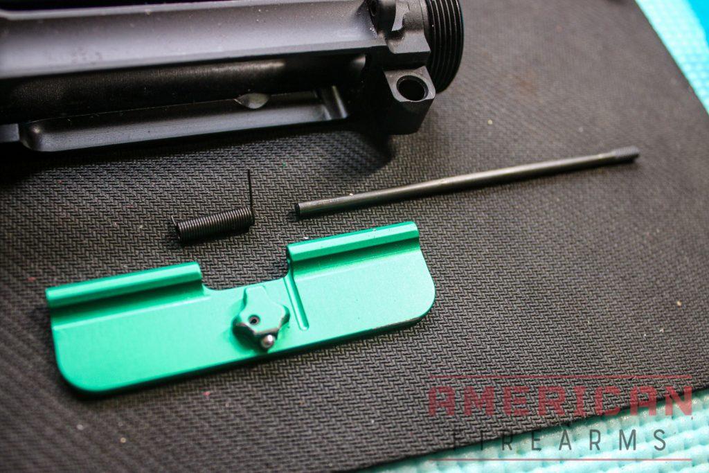
Parts Required:
- Ejection Port Cover
- Ejection Port Cover Pin
- Ejection Port Cover spring
Steps:
- Line up the ejection port cover with the holes on the upper assembly.
- Start by inserting the pin through the first side of the port cover.
- The spring can only be installed one way. The side of the spring with the longer piece goes on the right side into the port cover groove. Start sliding the spring onto the pin, but don’t install the pin all the way yet.
- The left side of the spring has to do one complete rotation to activate the “springiness” that makes the ejection port cover flip out. Using needle-nose pliers, grab onto the small end of the spring, rotate the spring, line it back up with the left side of the ejection port cover, push the pin through the rest of the spring, cover, and into the final hole.
- Believe it or not that is the most challenging part of assembling an AR-15.
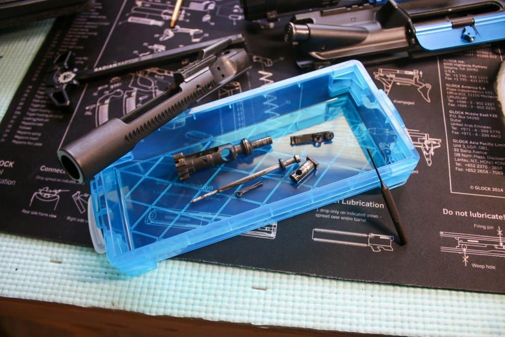
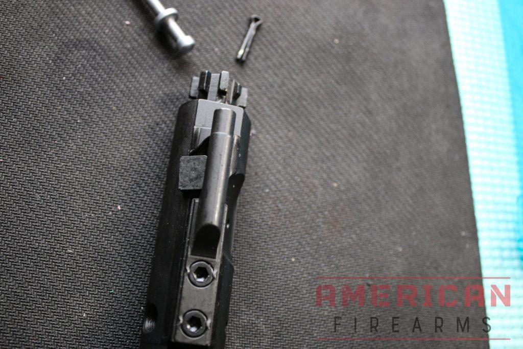
4. Assemble the Bolt Carrier Assembly
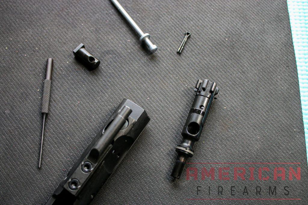
Parts Required:
- Bolt
- Firing Pin
- Cam Pin
- Firing Pin Retaining Pin
Steps:
- A bolt can only be inserted into the carrier one way. When looking at the bolt face, it looks like a gear with the ejector to the right side and extractor to the left. With this orientation, insert the bolt into the BCG.
- Insert the cam pin into the top of the BCG until it is flush and has gone through the bolt.
- Rotate the cam pin 90 degrees so the holes are aligned, and insert the firing pin into the BCG.
- Once the firing pin is in, insert the firing pin retaining pin from the larger opening on the side of the BCG. (015)
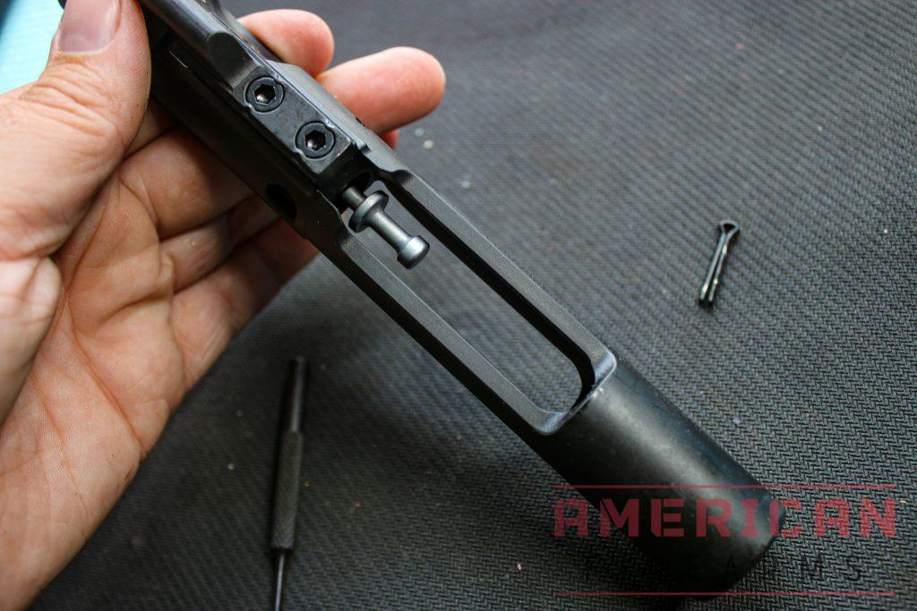
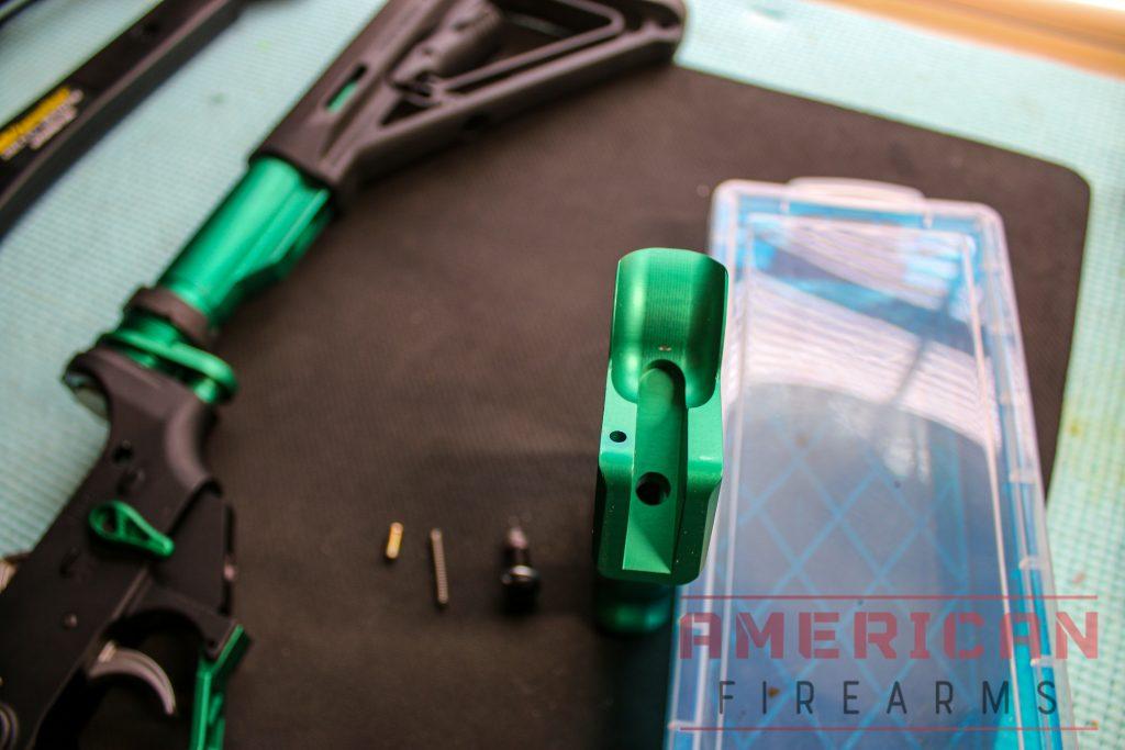
5. Assemble the Charging Handle Assembly
Parts Required:
- Charging handle
- Charging handle latch spring
- Charging handle latch roll pin
- Charging handle latch
Steps:
- With the variety of charging handles on the market today, not all of them will disassemble in this same way.
- Insert the charging handle latch spring into the side of the charging handle
- Insert the charging handle latch roll pin on the top of the charging handle, but only hammer in to get it started.
- Compress the charging handle latch into the side of the charging handle with the spring, make sure the holes are lined up, then hammer the roll pin in.
6. Install Charging Handle Assembly & Bolt Carrier Assembly
Parts Required:
- Charging handle
- Bolt carrier group
- Completed upper receiver
Steps:
- If you look at your charging handle, you’ll notice the two small side flairs on either side. Inside your upper receiver are two widened gaps where these notches line up. Insert your charging handle through these gaps so it lays flat into the upper receiver.
- The bolt in your bolt carrier group has to be stretched all the way out for it to go into the upper receiver assembly.
- Line up the gas carrier key onto the charging handle and slide both the BCG and handle in until you hear an audible click.
7. Installing the Upper Receiver into the Action Block and tightening it in the Vise
Parts Required:
- Receiver action block
- Upper assembly
- Vise
Steps:
- Wrap the receiver action block over your upper.
- Put the block in your vise and tighten it down. It needs to be tight enough to keep it secure while you’re torquing your barrel nut down.
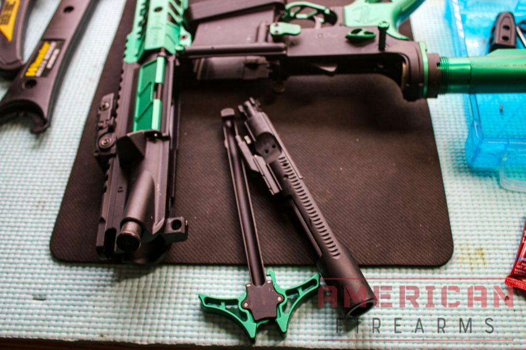
8. Install the Barrel
Parts Required:
- Upper receiver
- Barrel
Steps:
- Before installing a barrel, determine what the rifle’s purpose is. Chrome lining on a barrel will not last as long as match-grade stainless steel. If this AR-15 build is for competition, consider upgrading to the stainless steel barrel.
- The threads in your upper receiver have a square notch cut out, which is where your barrel will index for proper alignment.
- Push the barrel into this notch until the threads and barrel are flush.
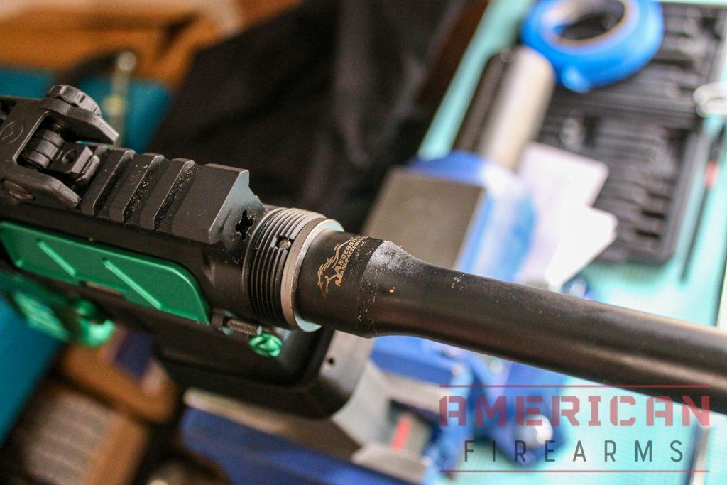
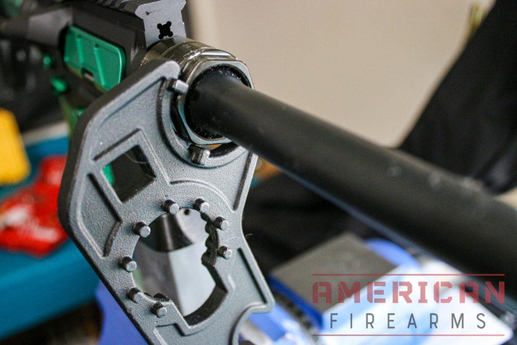
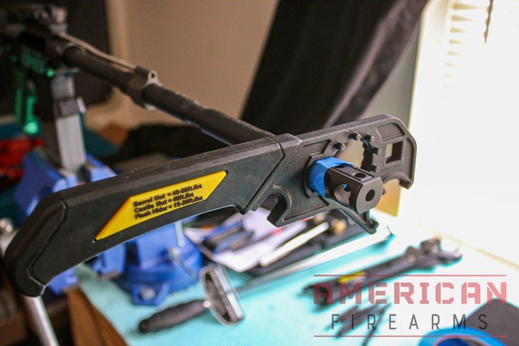
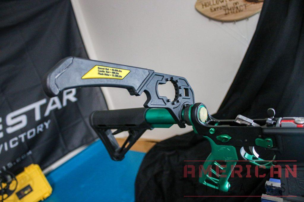
9. Install Outer Receiver Nut & Inner Barrel Retainer Nut
Parts Required:
- Barrel Nut
Steps:
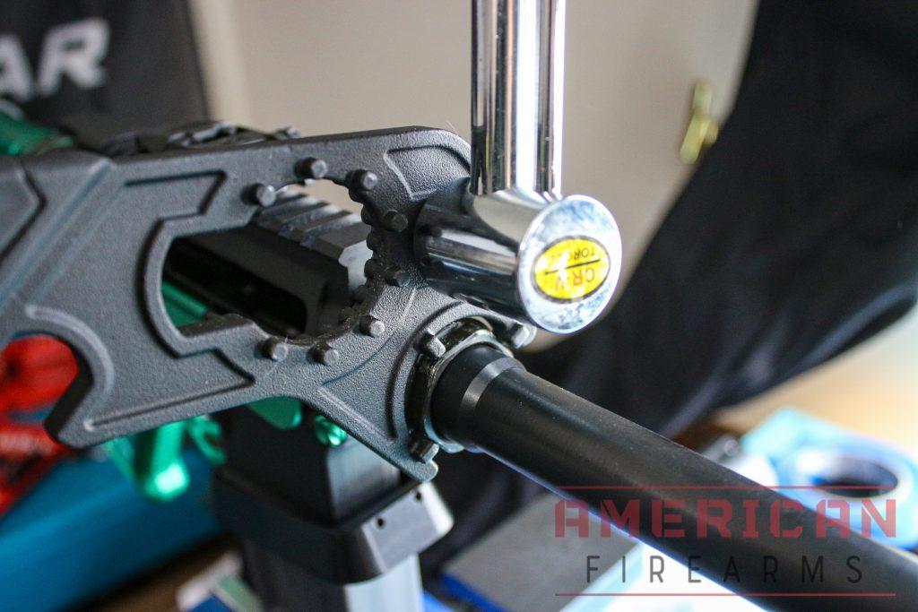
- Install the barrel nut by going over the gas tube until you get to the threads. If you have anti-seize, apply a little to the threads.
- Hand tighten the barrel nut.
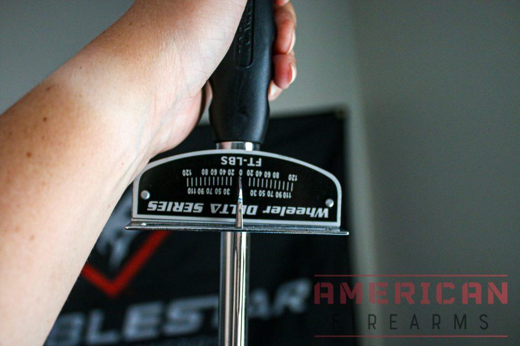
- Barrel nuts should be tightened down between 40 and 80 ft. lbs. If your barrel nut has specific torque specs, follow those instructions. Use an armorer’s wrench to grab onto the barrel nut.
- Attach your torque wrench to the armorer’s wrench.
- Tighten down the barrel nut until you have your desired ft. lbs.
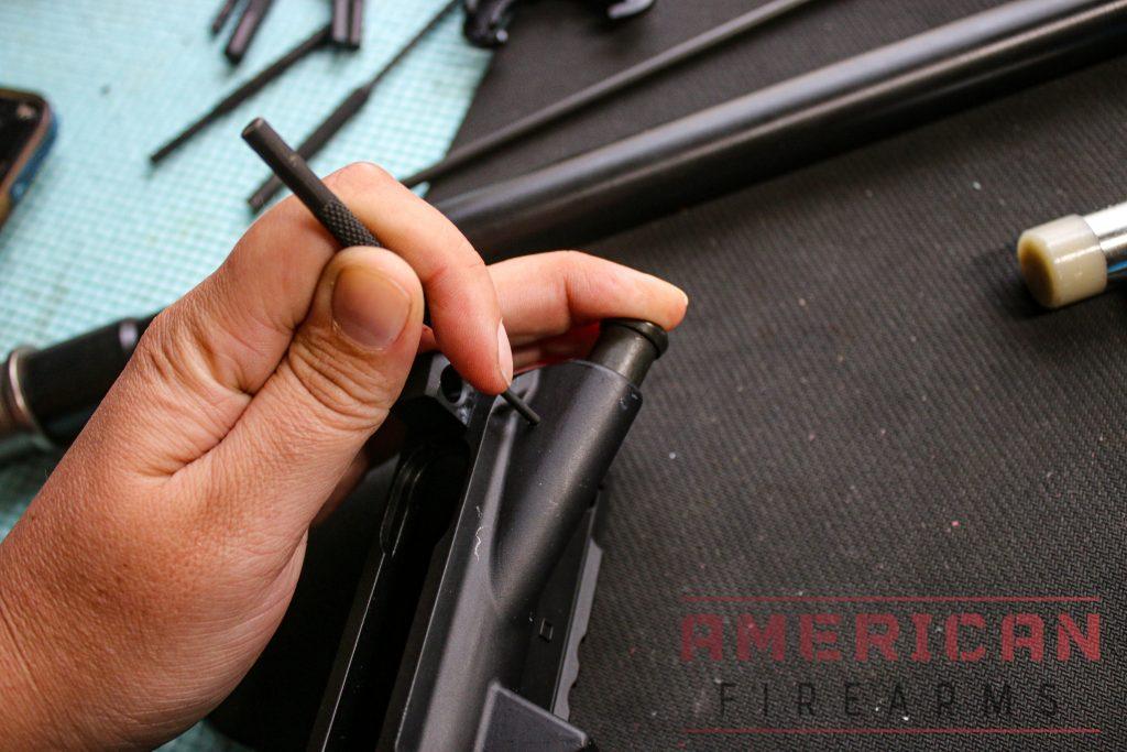
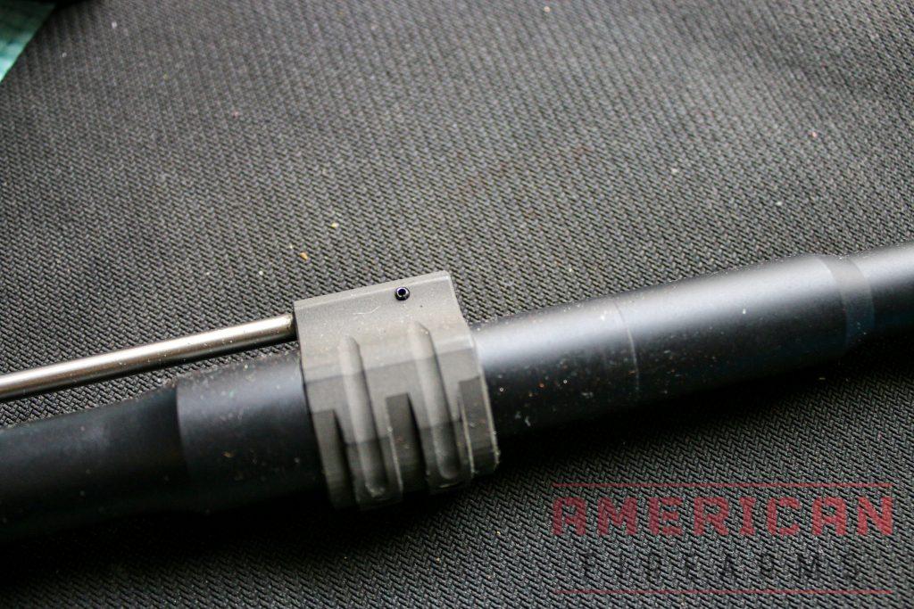
10. Installing the AR-15 Gas Tube and Gas Block
Parts Required:
- Gas tube
- Gas tube roll pin
Steps:
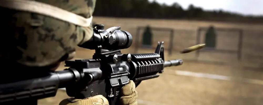
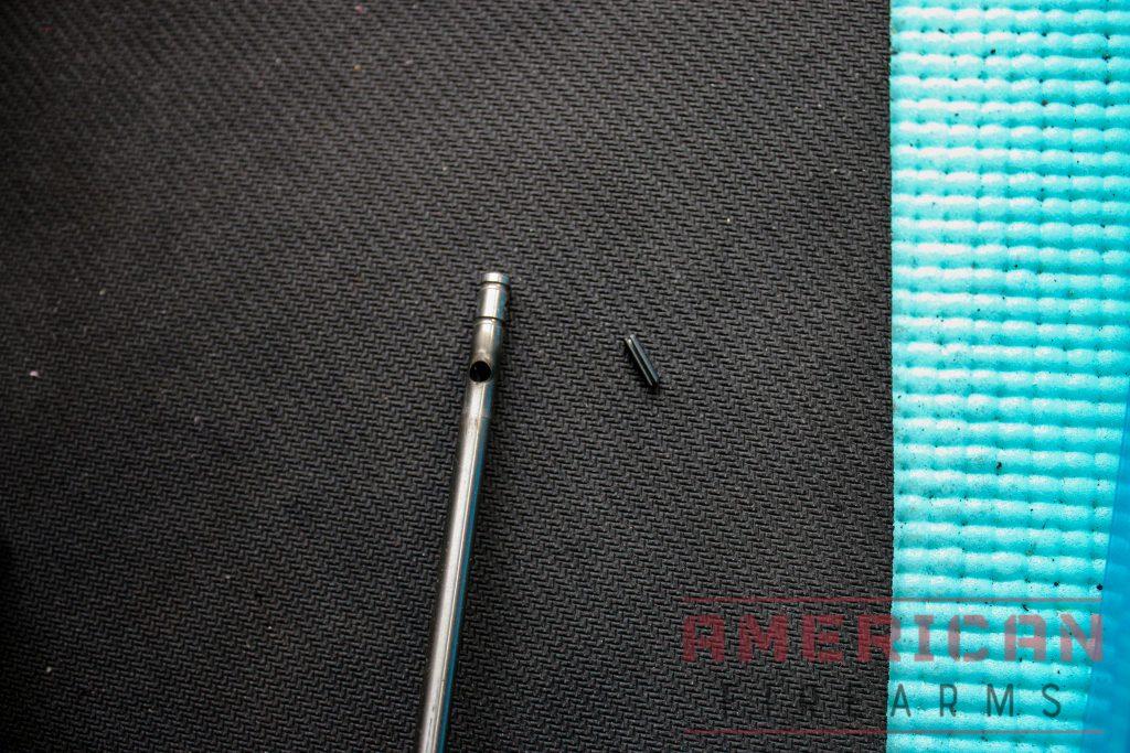
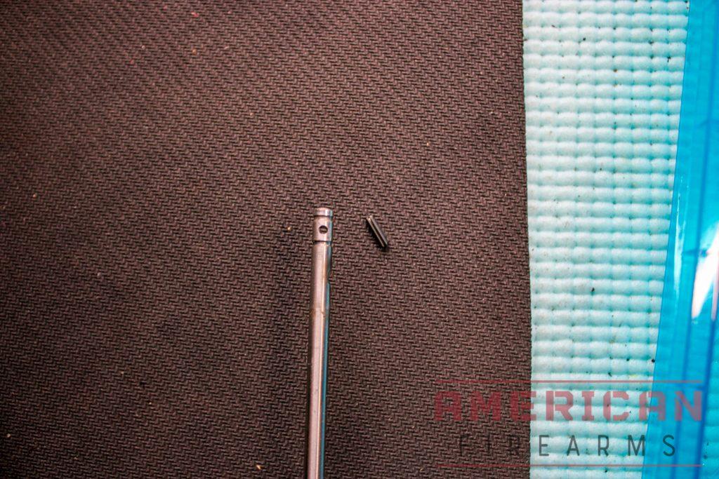
- Insert the open end of the gas tube into the hole on the upper assembly. This is what is called a direct impingement gas system. The gas from a fired cartridge goes through the tube into the bolt carrier and cycles the action that extracts and ejects the spent round to load another.
- Put your gas block onto your barrel and insert the other end of the gas tube into it. The gas system length is the distance from the barrel to the gas block and can increase or decrease felt recoil.
- The open hole on the gas tube should face down towards the barrel gas port, or your gas system will not work. (006)
- The gas tube then has a smaller hole open on both sides where the gas tube roll pin goes through the gas block and the tube. (004)
- Hammer the roll pin in until it is flush against both sides of the gas block (035)

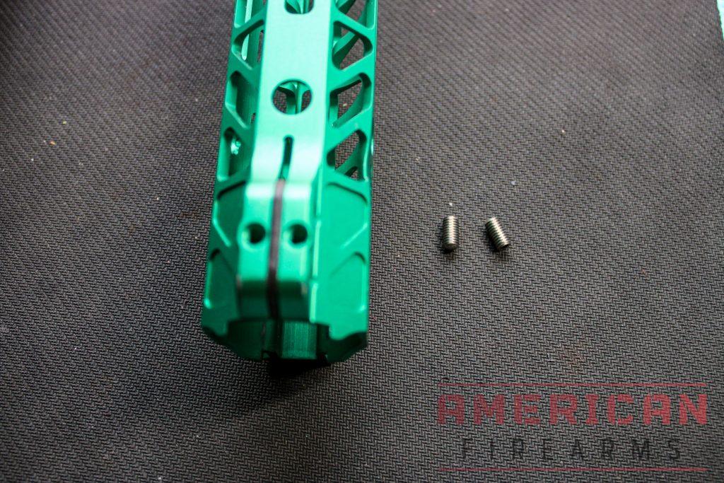
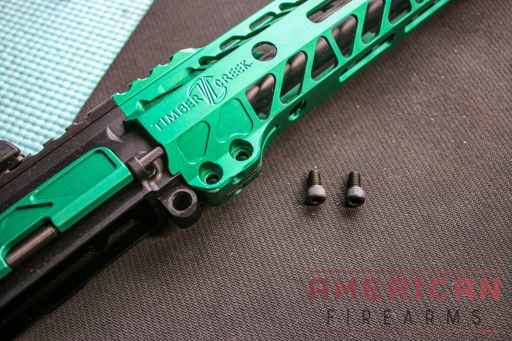
11. Install AR-15 Free Float Tube Handguard
Parts Required:
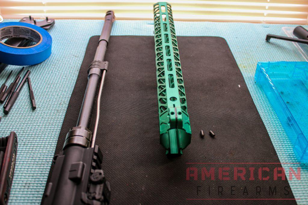
- Upper assembly with gas tube installed
- Picatinny Rail Handguard (and all parts that came with it)
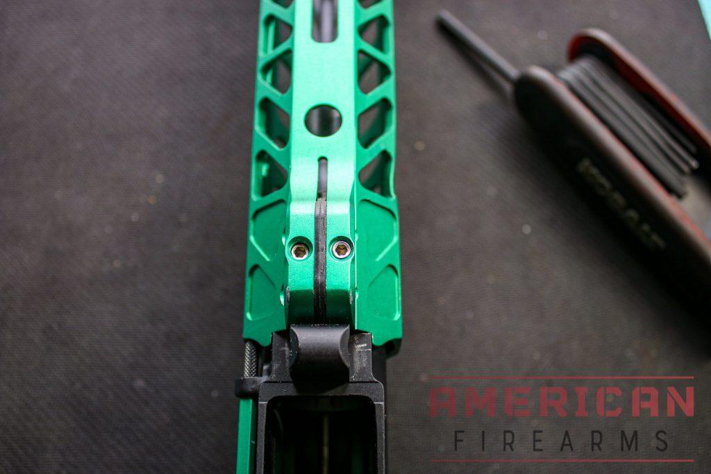
Steps:
- Slide the handguard over the barrel and onto the upper until it is completely flush. The barrel length will determine the size of the handguard you need.
- Apply thread locker to the two set screws and tighten down.
- Apply thread locker to the two side set screws and tighten down.
- The upper assembly is complete!
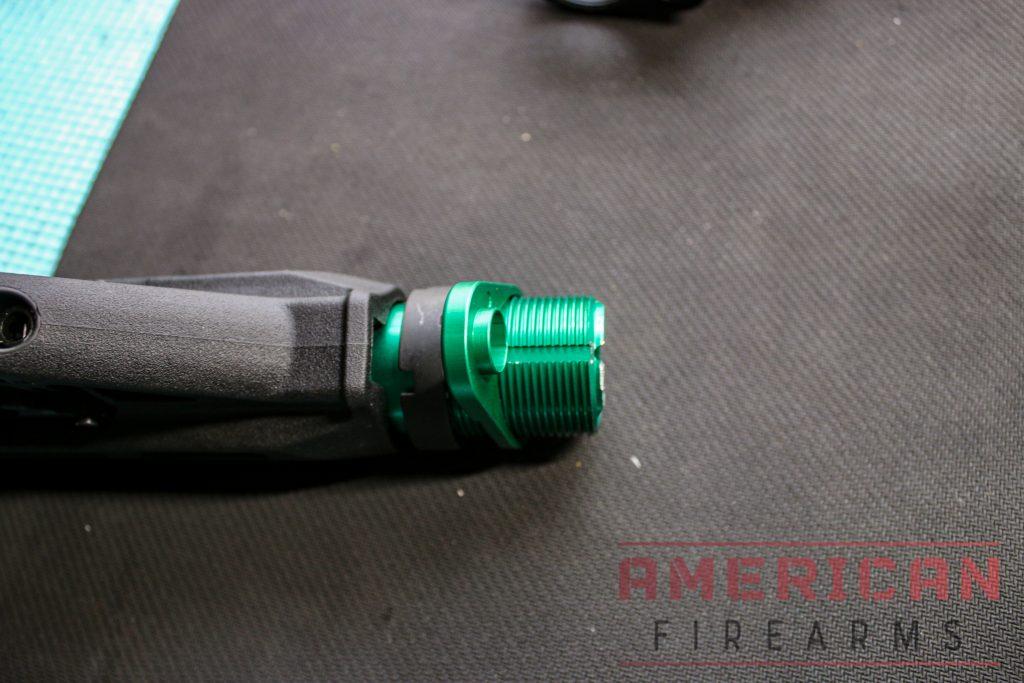
12. Install the flash hider
Parts Required:
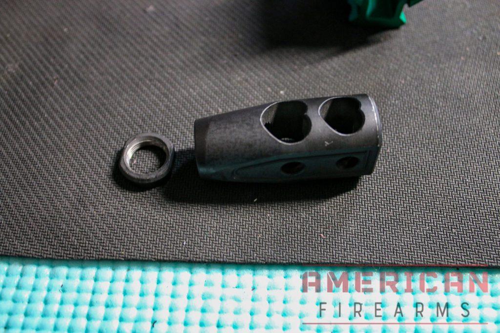
- Crush washer
- Flash Hider
Steps:
- Put the crush washer on the threaded barrel first, followed by the flash hider.
- Use your armorer’s wrench to tighten down the flash hider, so it is level with the barrel.
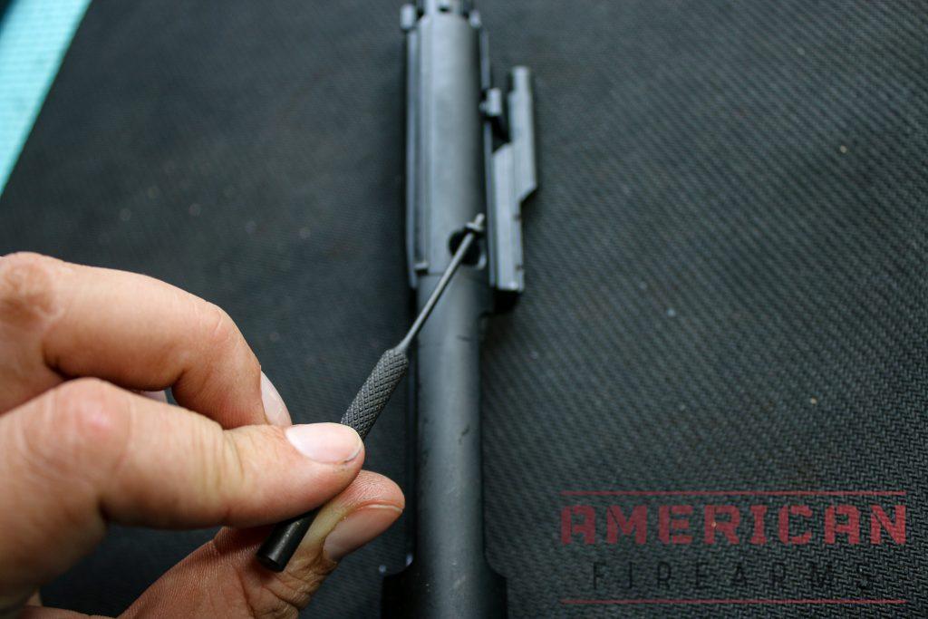
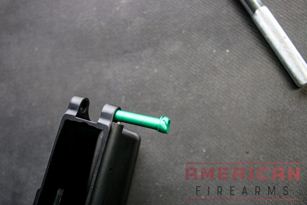
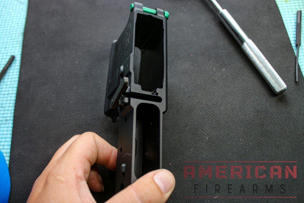
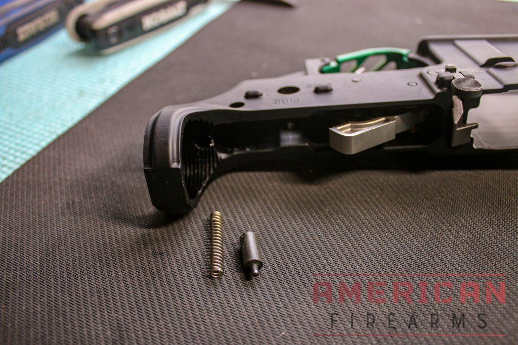
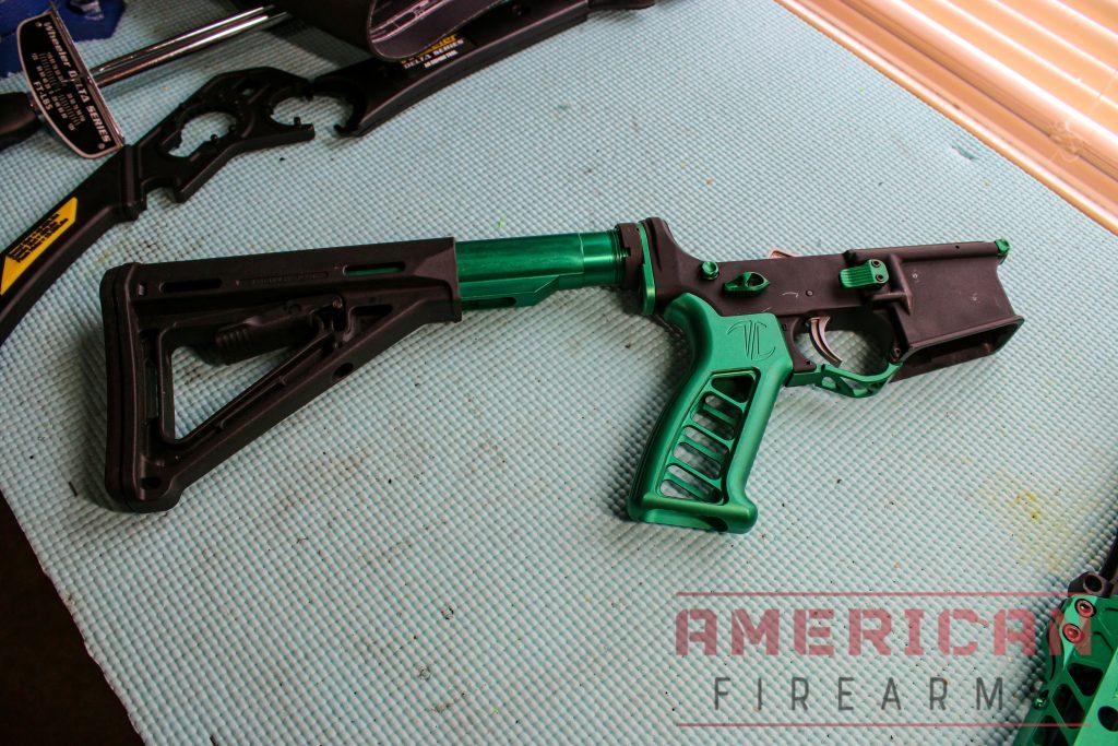
13. Install first pivot pin on the lower assembly
Parts Required:
- Detent
- Detent spring
- Pivot pin
Steps:
- This is where the pivot pin installation tool comes in handy.
- Insert the spring into the hole in the lower receiver.
- Put the detent on top of the detent spring, and using the pivot pin tool or something flat like a credit card, push the detent and spring down.
- Quickly press the pivot pin through the first hole without sending the detent and spring flying.
- Ensure it is installed by rotating it to ensure the detent is in the groove in the pivot pin.
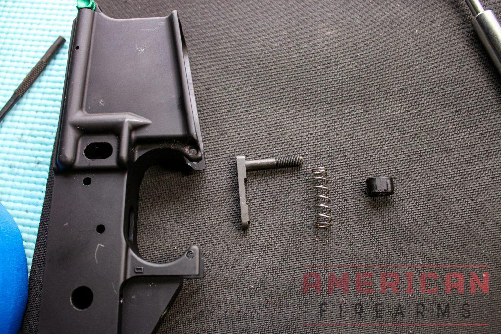
14. Install the magazine catch
Parts Required:
- Magazine catch
- Magazine catch spring
- Magazine catch button
Steps:
- Put the magazine catch spring over the catch and line it up to the other side of the lower.
- Attach the magazine catch button and press the catch into the button until the threads and screw line up.
- Tighten the catch by spinning it clockwise until the end of the catch is flush with the button. This may require you to push the button inward with a punch while tightening it down.
15. Install the bolt catch
Parts Required:
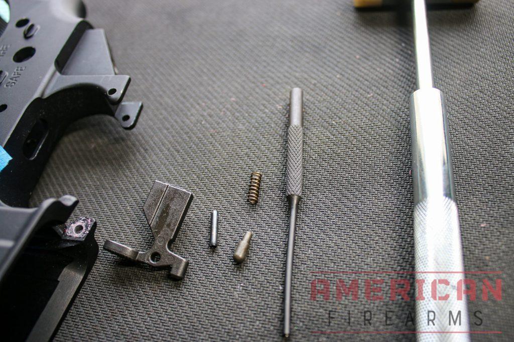
- Bolt catch button
- Bolt catch spring
- Bolt catch plunger
- Bolt catch roll pin
Steps:
- On the side of the lower, insert the spring into the hole first, followed by the plunger.
- You can use blue painter’s tape or something else to prevent the marring of the finish on the side of your lower.
- Hold down the bolt catch until the holes line up to insert the roll pin.
- Hammer the pin until it is flush.
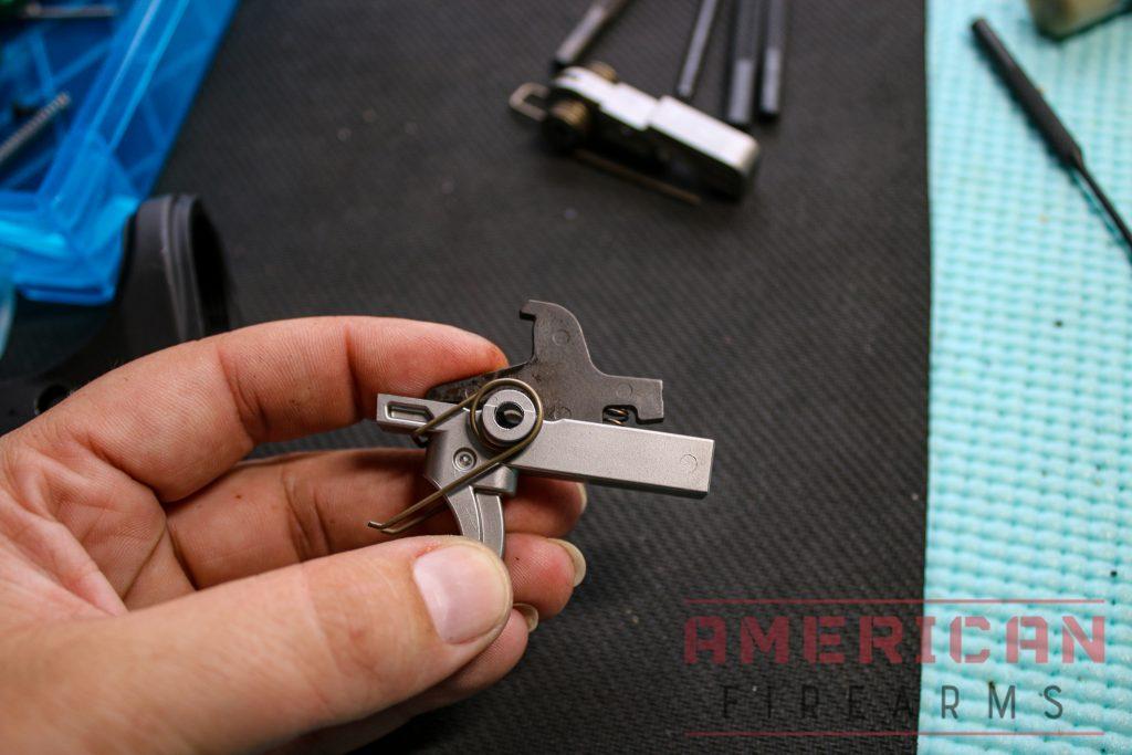
16. Installing a Mil-Spec trigger
Parts Required:
- Two trigger pins
- Trigger
- Trigger spring
- Disconnector
- Disconnector spring
- Hammer
- Hammer spring
Steps:
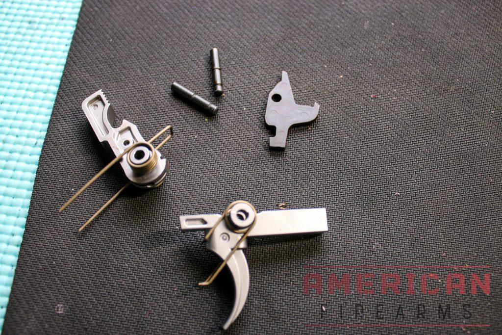
- Install the trigger spring onto the trigger, so it looks like an elephant with tusks.
- Install disconnector spring on top of the trigger (fat end of the spring down).
- Seat the trigger assembly into the lower receiver. (There’s only one direction a trigger can go in)
- Put the disconnector on top of the trigger.
- Assemble the hammer spring onto the hammer and load the spring so the hammer can activate rearward.
- Push down on the entire assembly until the holes line up with the lower. Use a pin punch to hold the top of the trigger assembly in place.
- Hammer in the lower trigger pin until it is flush.
- Hammer in the upper trigger pin. Both pins should be inserted from the same side.
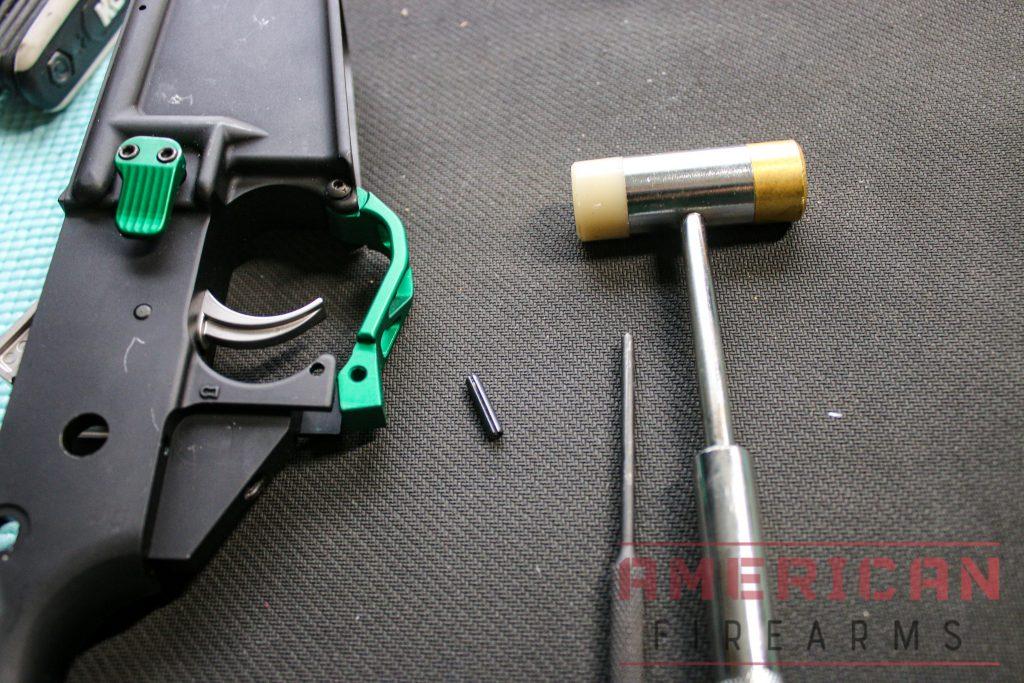
17. Install the trigger guard
Parts Required:
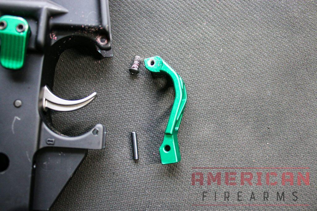
- Trigger guard
- Trigger guard screw
- Trigger guard roll pin
Steps:
- First, line up the trigger guard with the holes on the lower.
- Apply thread locker to the screw and screw it into the hole. (113)
- Next, line up the other holes and hammer in the roll pin to keep that end in place. (116)
- Protect the ears! The lower is most vulnerable to damage without something protecting the trigger guard assembly. Use the soft grips of needle nose pliers or something else to soften the installation as you hammer the pin in.
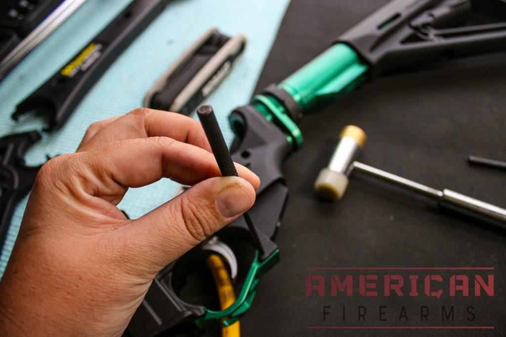
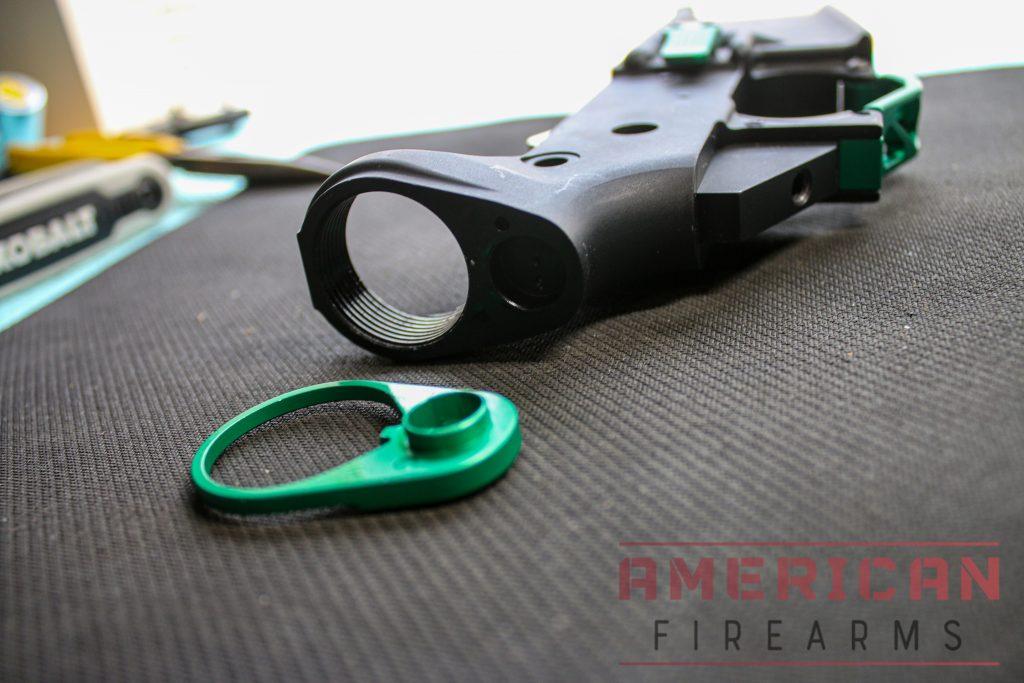
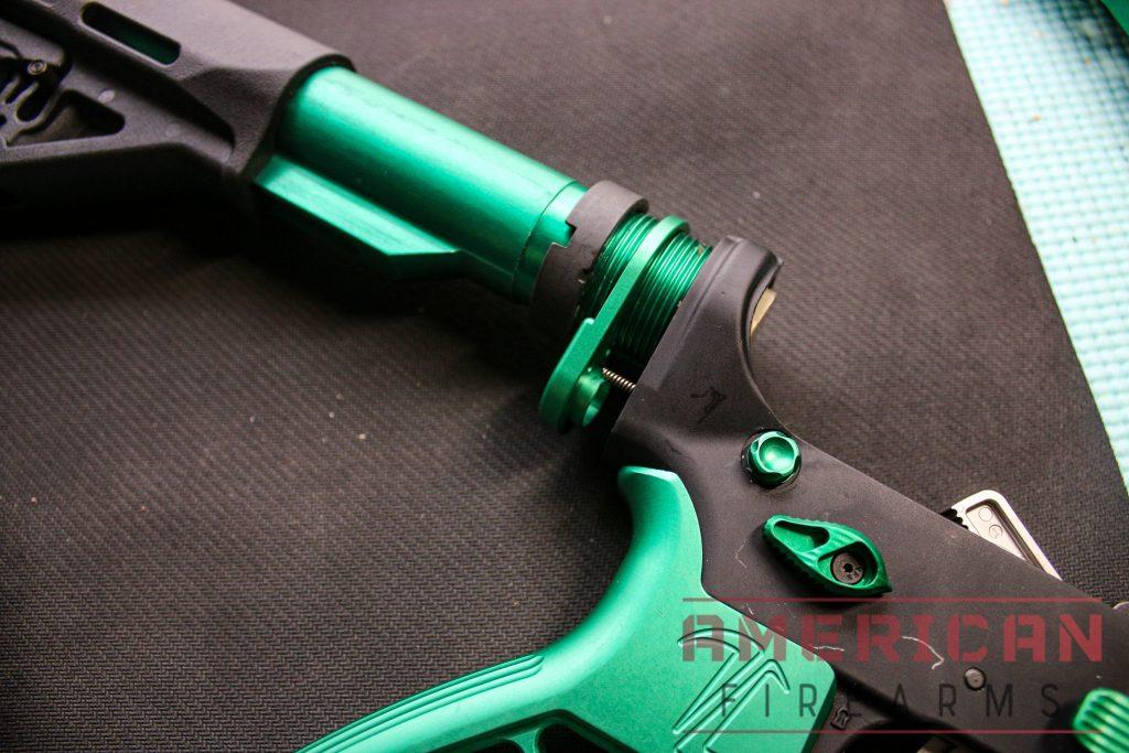
18. Install buffer tube and rear pivot pin
Parts Required:
- Buffer tube
- Buffer retainer
- Buffer retainer spring
- (Optional) QD attachment
- Castle Nut
- Rear pivot pin
- Detent
- Detent spring
Steps:
- Screw the castle nut onto the buffer tube.
- Slide the QD attachment onto the buffer tube with the protruding side facing the lower.
- In the lower receiver, put the buffer tube retainer spring into the hole and the buffer retainer on top of it. (108-112)
- Insert the rear pivot pin into the lower assembly.
- Start screwing the buffer tube onto the lower receiver. (121)
- Leaving a gap between the QD attachment and lower, insert the detent first, followed by the detent spring. (126)
- Hold the QD attachment in place against the lower while screwing the buffer tube into place until the buffer retainer is prevented from springing upward.
- Hand tighten the castle nut.
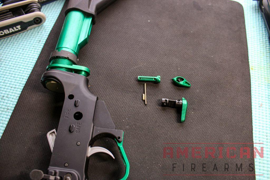
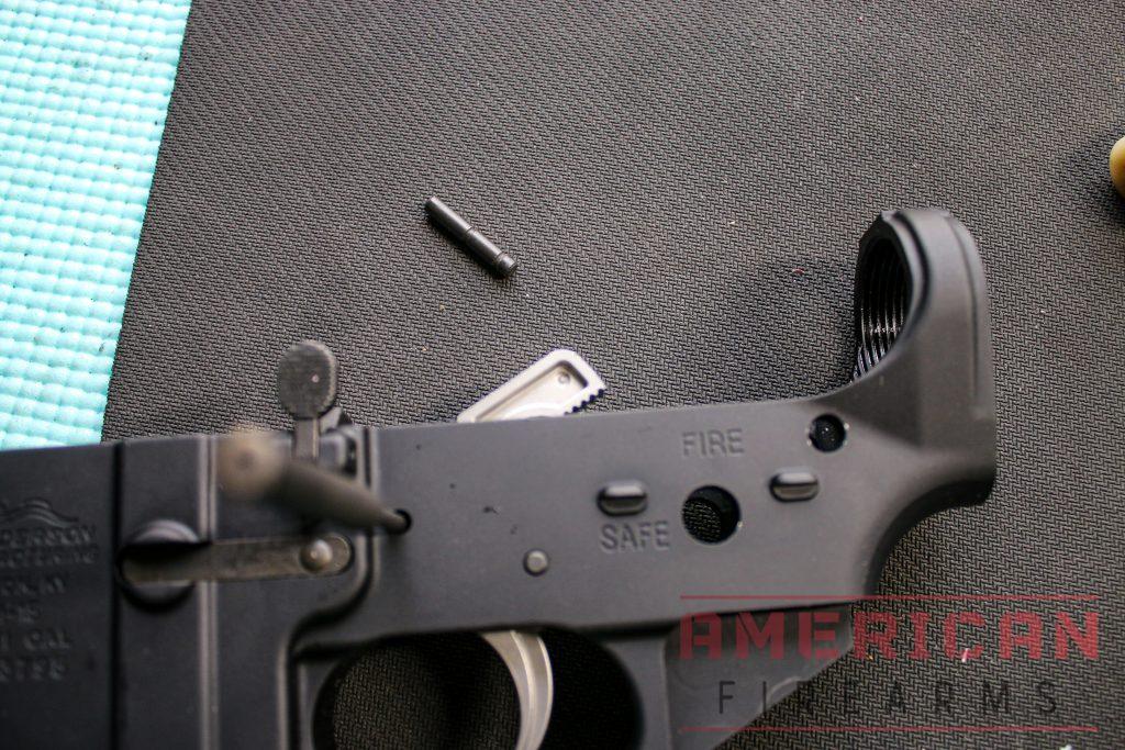
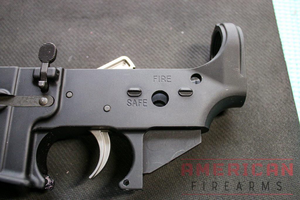
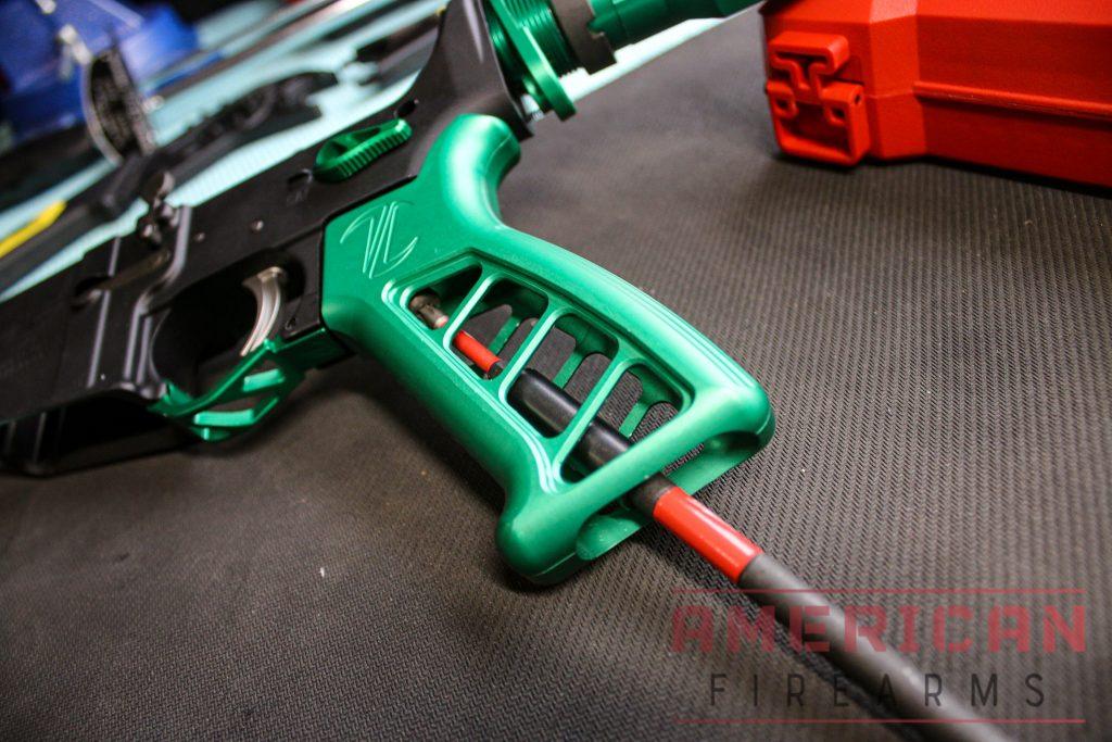
19. Install safety selector and grip
Parts Required:
- Safety selector
- Safety detent
- Safety spring
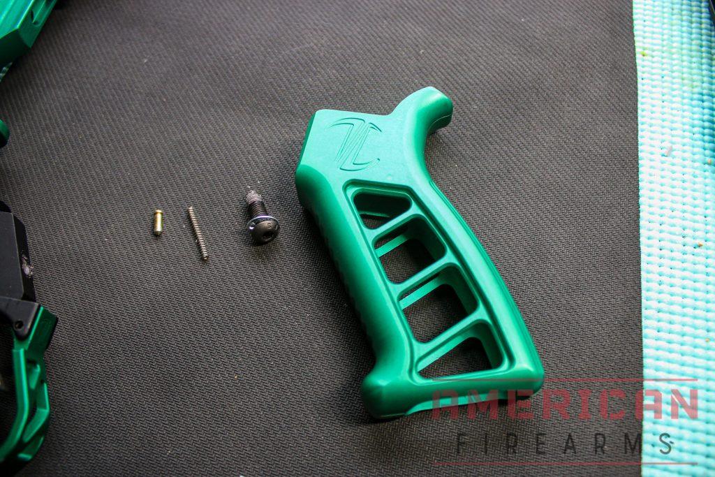
- Grip
- Grip screw and washer
Steps:
- Insert the safety selector into the lower receiver.
- On the bottom of the lower is a hole where the safety detent goes. Insert the detent pointy end down.
- If you look at the top of your grip, you’ll see a small hole on top. Insert the safety spring into the hole. (122)
- Install the grip, be careful to push down as you screw in the grip screw to prevent the safety spring from coming out. (124)
20.
Install buffer spring and buffer and tighten
Parts Required:
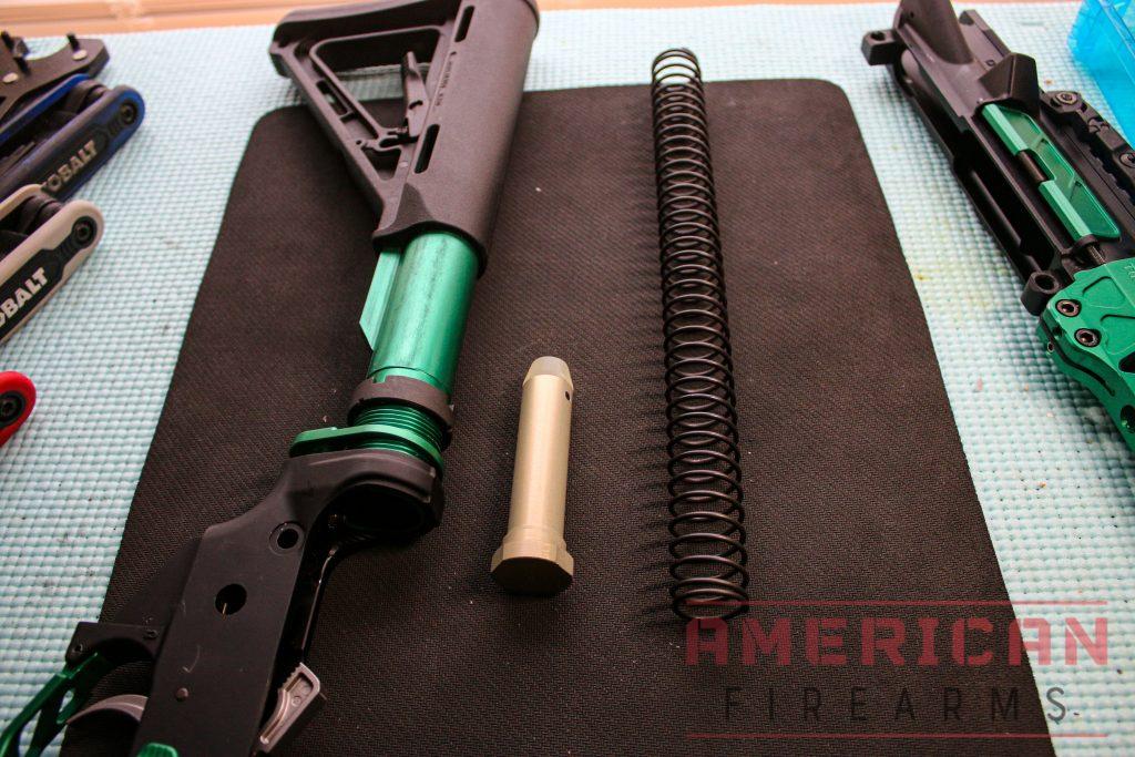
- Buffer
- Buffer spring
Steps:
- Insert the buffer spring over the buffer.
- Push the buffer assembly into the buffer tube until it catches on the buffer retainer.
- Use your armorer’s wrench to tighten the castle nut to 40 ft. lbs.
21. Install sights
Parts Required:
- Front sight
- Rear sight
Steps:
- Iron sights are easy to install on a Picatinny rail handguard. Install both of the iron sights onto the rail with as much distance between them as possible. The rear sight should be the peephole, with the front sight as a notch or post.
- Tighten the side screws to prevent movement.
22. Perform a function test
Now that both assemblies are complete put them together and push the pivot pins through. Test out the trigger with the safety on to ensure the hammer doesn’t fall. Test the trigger pull with the safety off as well as the trigger reset.
That's a wrap!
Additonal Reading
- Aero Precision: AR-15 Barrel Nut Installation
- 80% Lowers: AR-15 Barrel Steels & Coatings Explained
- Brownells: How To Use the Brownells AR-15 Pivot Pin Detent Tool
Sign up for our newsletter
Get discounts from top brands and our latest reviews!